


My final-year project: steering a UV laser for trapped ions
I had barely used a laser when I joined a trapped-ion lab. I built a two-axis beam-steering setup at 355 nm, lost the alignment over the December break, rebuilt it in three months, and later worked out what really limited it.
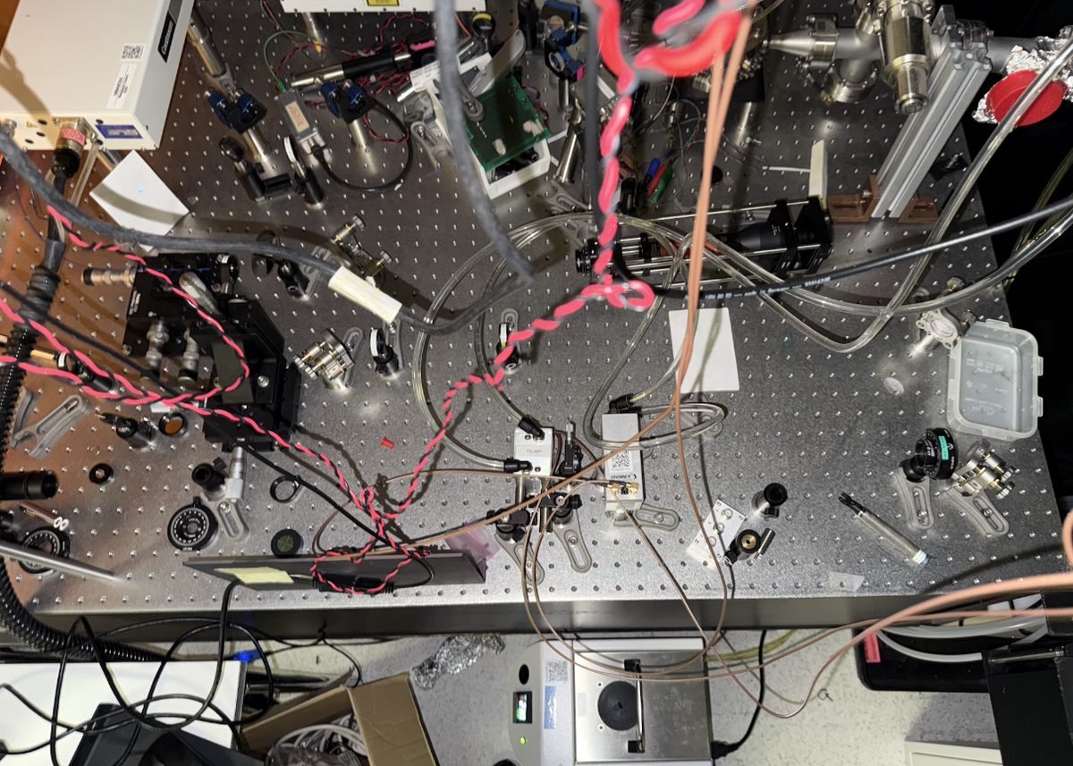
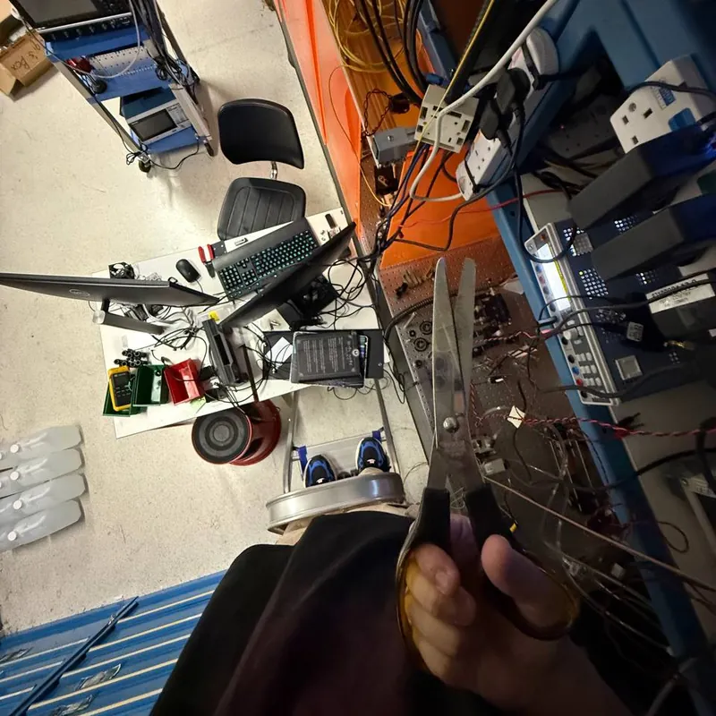
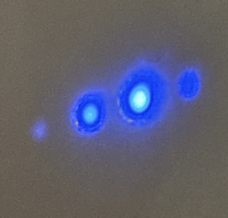
It has been a year since I graduated, and it finally feels like the right time to write about my final-year project. I started it in August 2024 (PH4421), in Assoc. Prof. Dzmitry Matsukevich’s trapped-ion lab at the Centre for Quantum Technologies, with Assoc. Prof. Rainer Dumke as co-supervisor. It was the first time I ran my own experimental project in a research group. I chose the lab because I wanted to see how trapped-ion experiments actually work, not only read about them. The catch: apart from our undergraduate lab course, I had never worked with a laser. I came in knowing little about laser physics and less about building an experiment, and over the year I built the setup in the photo above from scratch, with the postdoc and PhD students in the group to ask when I got stuck.
The full thesis, with all the data, is on DR-NTU [1], and the talk is on YouTube [2]. This is the short version, plus one thing I only understood later.
One laser, one ion
A trapped-ion quantum computer holds a row of charged atoms in a Paul trap. An oscillating radio-frequency field confines them radially and static voltages hold them along the trap axis, so they settle into a line 3 to 10 µm apart [3]. Each ion is a qubit. To run a gate on one ion, you shine a laser on that ion and not its neighbours, and to run a program you have to move the beam from ion to ion in microseconds.
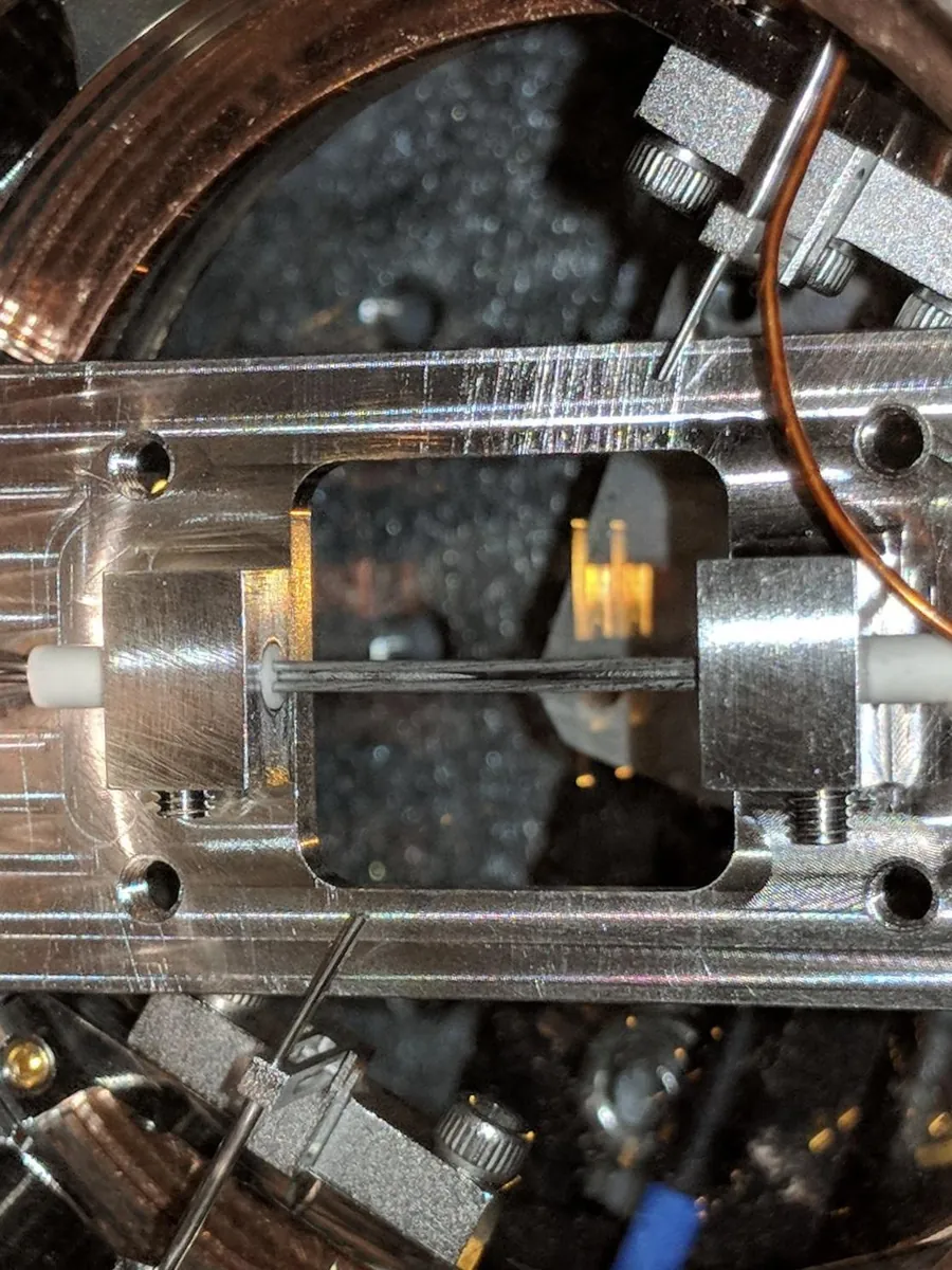
An acousto-optic deflector (AOD) does the moving. An RF signal drives a piezo on a crystal and launches a sound wave through it. The sound wave acts as a moving diffraction grating, and it bends the laser by an angle proportional to the RF frequency, θ ≈ λf/v, where λ is the laser wavelength and v the speed of sound in the crystal [4]. Change the frequency and the beam moves, with nothing mechanical involved, in a fraction of a microsecond. Two AODs at right angles steer in two dimensions. This is not only a lab technique: IonQ’s commercial Forte systems use AODs to steer their gate lasers onto individual ions [5].
My job was to build that crossed-AOD system at 355 nm and measure what it could do: how much light it deflects, how far the beam moves per MHz, how clean the spot stays, and how many separate positions it can address. Putting it in front of real ions was the next stage, not part of the project.
What I built
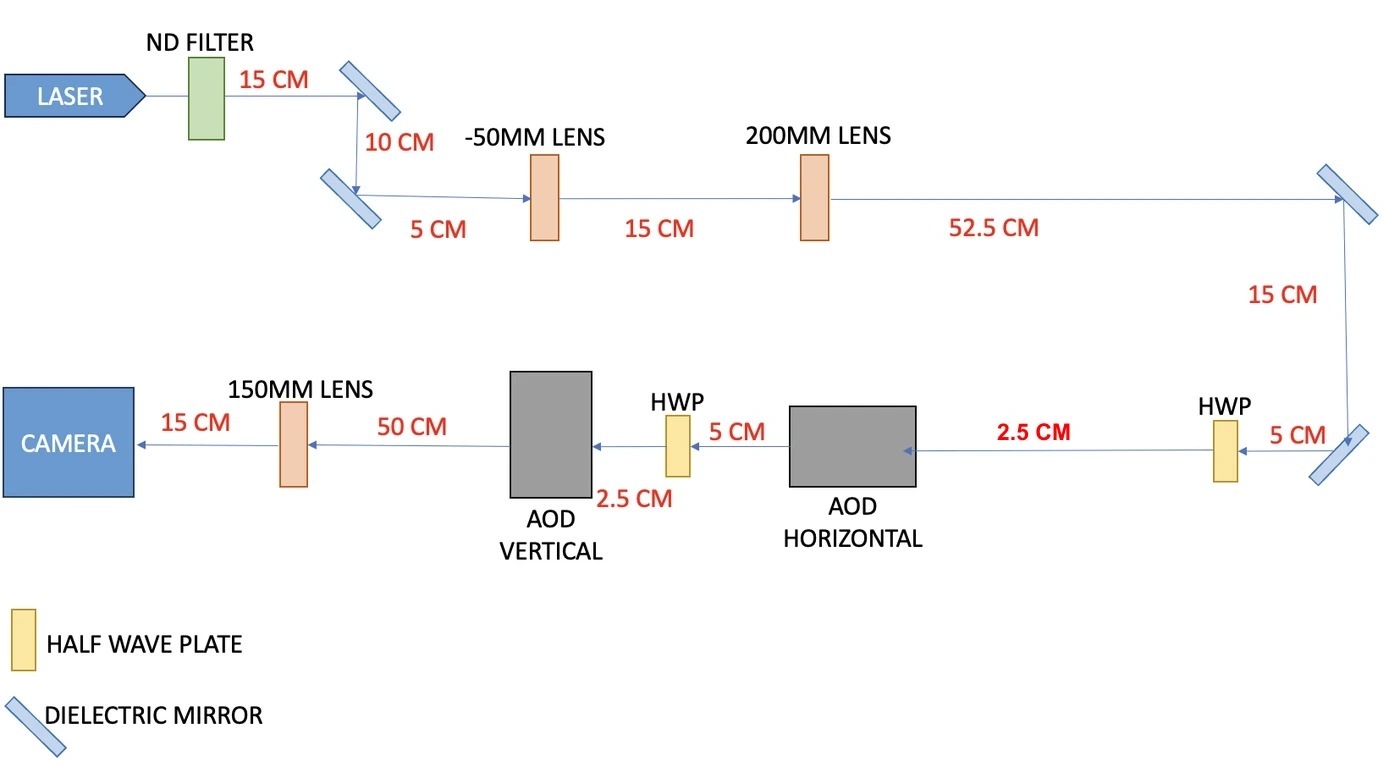
The optical side: a 4 W, 355 nm picosecond laser (a Coherent Paladin Compact [6]) delivered through a hollow-core fibre, a neutral-density filter wheel, a −50 mm and +200 mm lens pair to expand the beam four times, dielectric mirrors, a half-wave plate before each AOD to match its polarisation, two quartz AODs from ISOMET (centred at 170 MHz, with 80 MHz of bandwidth [7]), then a 150 mm lens and a camera with 2.2 µm pixels.
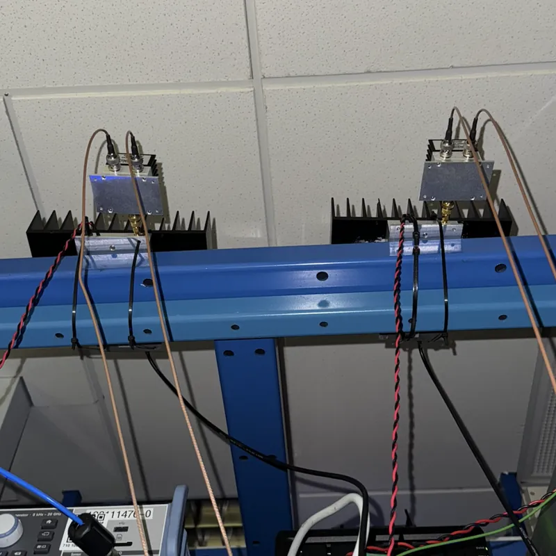
The RF side: a two-channel Windfreak synthesiser, a bandpass filter, splitters, two Mini-Circuits power amplifiers on heatsinks, and high-power splitters feeding both transducers of each AOD. Watts of RF in a crystal make heat, so the AOD mounts sat on water-cooled heat sinks connected to a chiller held at 23 °C. I checked each stage of the RF chain on a spectrum analyser before it went anywhere near an AOD.
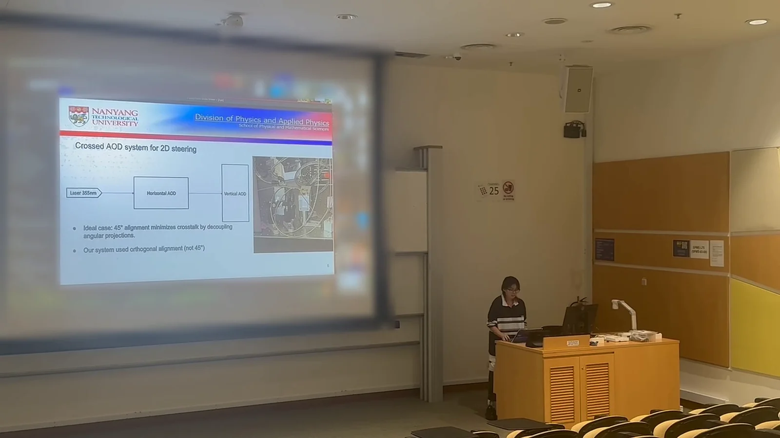
Not everything went to plan. There were no quarter-wave plates available, so I set the polarisation with half-wave plates only. The recommended arrangement mounts the crossed pair at 45°, which decouples the two scan axes and reduces crosstalk between the diffraction orders; that needed a custom rotation stage that could not be made in time, so mine sat square to the table. And the camera ended up rotated by 90°, so horizontal deflections showed up as vertical ones on screen.
Then the lab warmed up
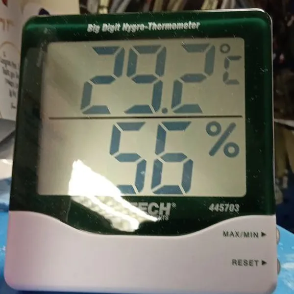
By November 2024 the system was built and aligned, and what was left was taking the data. Over the December break, the lab’s air-conditioning went down. The room, normally around 20 °C, went up to around 29 °C [1] and the cooling lines started collecting condensation. Both the laser and the AOD crystals are sensitive to temperature, and when I came back in January, the alignment was gone.
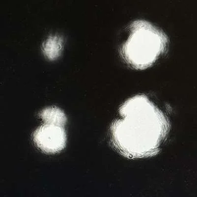
That left January to March to rebuild the alignment, take every measurement and write the thesis, with the temperature still not fixed. I presented on 21 April 2025. I got the data, but not in the conditions I wanted, and the beam was never as well prepared as it should have been.
What worked
Three results held up despite the conditions.
First, the diffraction efficiency. At 10 W of RF, the vertical AOD put 60.0 ± 1.1% of the light into the first order [1], against about 70% on the datasheet’s estimated scan response at that power [7]. The efficiency peaked between 170 and 180 MHz and fell off towards the edges of the band, the same shape as the datasheet curve. The AODs are designed for about 20 W of RF drive [7]; I never drove them above 10 W.
Second, the steering. The deflection angle was linear in RF frequency from 130 to 210 MHz, with R² ≥ 0.996 for each AOD on its own [1]. Driving both AODs together moved the beam along the diagonal at the rate the vector sum of the two predicts.
Third, the stability. The spot size stayed within ±4.5 µm across the whole frequency sweep, and did not change between 5 W and 10 W of drive [1].
Five spots instead of a hundred
The number that looked bad was resolution: how many separate spots the system can address across its frequency range. ISOMET quotes up to 100 for these AODs [7]. At my camera, I could fit four to five.
The formula behind it: the number of resolvable spots is the scan angle, λΔf/v, divided by the beam’s own divergence, λ/πw for a Gaussian beam, so N = πwΔf/v, where w is the beam radius inside the crystal, Δf the RF bandwidth (80 MHz) and v the speed of sound in quartz (5.7 mm/µs) [4]. Stricter resolution criteria halve N; they do not change the ratios below. A wider beam diverges less, so more spots fit into the same scan. ISOMET’s 100-spot figure goes with its 7 mm aperture, which it calls optimal for a 5 mm beam [7].
In the thesis [1], and in the talk, I plotted this formula, put my ~100 µm spot on it, found it landed on the line at about five, and concluded that beam size explained the whole gap. Looking at it again a year later, I had used the wrong beam. The ~100 µm was the spot on the camera; the formula needs the beam inside the crystal. Mine was 1.8 mm across (a radius of 889 µm) going into the first AOD. That is 36% of the design size, and it caps the system at about 39 spots, not five. So beam size explains a factor of three. What explains the rest?
Two other numbers in the thesis looked wrong, and at the time I blamed each on something different. The deflection per MHz came out 5 to 8 times below theory, which I put down to a possibly mislabelled lens. And the spots on the camera were about 100 µm, while a 1.8 mm beam through a 150 mm lens should focus to about 19 µm. One cause fits both: the camera was not at the focus of the lens. Part of the slope error was also in how I turned pixels into angles. At the focal plane, position equals focal length times angle, so the distance to divide by is the 150 mm focal length; I divided by the distance from the AOD to the camera, 650 to 750 mm.
Put the camera about 1.8 cm behind the focus and the numbers line up. The spot grows from 19 µm to about 108 µm; I measured 108–110 µm for the undeflected beam. The same offset predicts that the spots move 0.64 and 0.72 times as far per MHz as they would at the focus, for the horizontal AOD, 60 cm before the lens, and the vertical AOD, 50 cm before it; I measured 0.63 and 0.74. So the AODs were deflecting at the theoretical 0.062 mrad per MHz [7], to within how well I knew my distances. Bigger spots moving shorter distances: 39 becomes about five. I never measured where the camera sat relative to the focus; this is where the numbers point.
So the conclusion of the thesis stands, with better reasons behind it. The AODs did what the datasheet says. What fell short was the optics around them: a telescope too weak to bring the beam up to the 5 mm the AODs were designed for, and a camera sitting off focus, in a lab at around 29 °C.
What I would do differently
Looking back, five changes would have made the biggest difference.
First, I would calculate the beam through the whole path before placing anything: its size and where it focuses after every lens, using the real distances between each lens and mirror, and then put the optics where the calculation says. The focus in my setup was clearly off. A Gaussian-beam calculation on paper would have caught it, and would have shown that a four-times telescope could not bring the beam anywhere near the 5 mm the AODs are designed for [7].
Second, I would check the focus at the camera before measuring anything, by moving the camera along the beam until the spot is smallest, and I would convert pixels to angles with the lens’s focal length.
Third, I would log the lab temperature with every run, so that thermal drift shows up in the data rather than in hindsight.
Fourth, I would drive the AODs closer to their 20 W design power [7], through short RF cables. Mine were 2 m long, and standing waves in them may account for some of the ripple in the efficiency curves [1].
Finally, I would order the 45° rotation mount at the very start, since custom parts took the longest to arrive.
What came next
The project is also how I ended up doing a PhD. Rainer, my co-supervisor, contributed a lot to it, and through it he offered me a place in his group, which works on superconducting qubits.
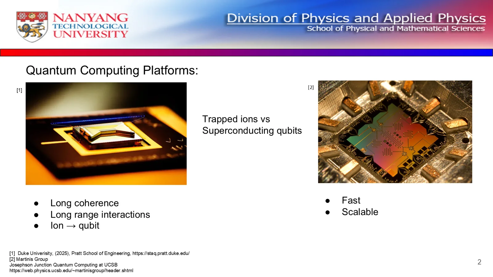
Switching platforms was part of the appeal. The second slide of my FYP talk compared the two: trapped ions have long coherence times and long-range interactions, while superconducting qubits are fast and scalable.
After a year of lasers and ions, I found I was more curious about the other side: qubits on a chip, driven by microwave electronics with FPGAs doing the control, and the question of how to go from a few of them to many. It is also what IBM [8], Google [9] and Rigetti [10] build their processors on, though trapped ions have strong companies of their own, such as IonQ [5] and Quantinuum [11].
I joined Rainer’s group as a PhD student in August 2025 (what I work on now). How I applied is a story for another post.
References
- M. Lee, Individual Addressing of a Linear Chain of Ions Using a Crossed AOD System, final-year thesis (PH4421), Nanyang Technological University, 2025. DR-NTU ↗
- M. Lee, final-year project talk, NTU, 21 April 2025; recording edited to remove the Q&A. YouTube ↗
- D. J. Wineland, C. Monroe, W. M. Itano, D. Leibfried, B. E. King and D. M. Meekhof, “Experimental issues in coherent quantum-state manipulation of trapped atomic ions,” Journal of Research of the National Institute of Standards and Technology 103, 259 (1998). doi:10.6028/jres.103.019 ↗
- B. E. A. Saleh and M. C. Teich, Fundamentals of Photonics, 3rd ed., Wiley, 2019: the chapters on beam optics and acousto-optics. Wiley ↗
- IonQ, “Introducing IonQ Forte, improving quantum performance with a software-enabled dynamic laser system,” 17 May 2022. ionq.com ↗
- Coherent, Paladin Compact 355-2000/4000 datasheet: 355 nm, more than 4 W, 120 MHz, 15 ps pulses (the pulse width is specified at the 1064 nm fundamental). PDF ↗
- ISOMET, D1384-aQ170-7 High Power Acousto-Optic Deflector (preliminary datasheet): 170 MHz centre, 80 MHz bandwidth, 7 mm aperture optimal for a 5 mm beam, about 20 W RF drive, up to 100 resolvable spots. PDF ↗
- IBM, “IBM Quantum hardware and roadmap.” ibm.com ↗
- Google, “Meet Willow, our state-of-the-art quantum chip,” December 2024. blog.google ↗
- Amazon Web Services, “Amazon Braket launches Rigetti Cepheus-1-108Q superconducting device,” AWS Quantum Technologies Blog, 2026. aws.amazon.com ↗
- Quantinuum, “Introducing Helios: The Most Accurate Quantum Computer in the World,” 5 November 2025. quantinuum.com ↗